| MENU ... |
 |
 |
|
|
|
|
|
|
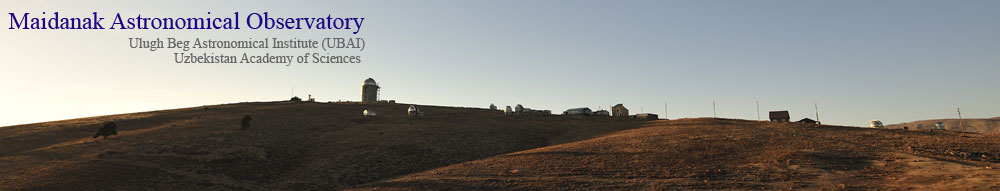
| MAIDANAK |
|
|
Longitude: 66° 53' 47''
Latitude: 38° 40' 22''
Altitude: 2593 m
Phone: +998 95 5050683
SMS alert:
Phone: +998 95 1423358
Phone: +998 95 1773116
E-mail: 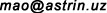
E-mail: 
Host institution: UBAI
|
|
| UBAI |
|
|
33 Astronomicheskaya str.,
Tashkent, 100052, Uzbekistan
Phone: +998 71 2358102
Fax: +998 71 2344867
E-mail: info@astrin.uz
|
|
|
| TELESCOPES & Instrumentation |
|
|
| Telescopes |
|
- AZT-22
 |
 |
AZT-22 1.5m telescope
Optical configuration:
Ritchey-Chretien f/7.74, D=1.5m
Equipment:
SI 600 Series 4096x4096 CCD (SNUCAM)
FLI MicroLine 3056x3056 CCD
Automatic guiding system
|
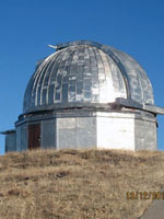
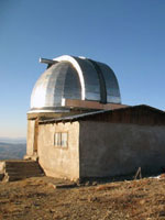
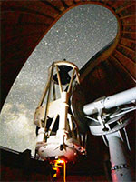
The main instrument of Maidanak Observatorys 1.5 meter RC telescope (AZT-22) manufactured by optical firm LOMO (Russia, S-Peterburg).
Telescope has been operational since 1992 year.
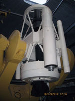
Optical shop test confirmed the high quality of the optical system AZT-22 limited diffraction optics. The 1.5-meter telescope was installed
in the dome equipped with ventilator system for the smoothing of the inside dome turbulence. The isolated summit Mt.Maidanak (2600 meter)
have good astroclimatical parameters: 2000 clean observational hours per year and mean seeing (FWHW) is about 0.7 arcsec (Artamonov et al. 1987, Ehgamberdiev et al. 2000).
(read more ...)
The excellent 1.5 meter telescope, good seeing and a large number of clear nights make possible the long-term monitoring of gravitational lenses system (GLS).
The collaboration were carried out by three groups from Ulugh Beg Astronomical Institute (Tashkent, Uzbekistan), Astronomical Observatory of National Kharkov University (Ukraine)
and Sternberg Astronomical Institute of Moscow State University (Russia) for making of monitoring selected GLS. Because of technical reasons, we had to use three different CCD cameras
in our observations, Pictor-416 camera in 1995, Pictor-416 and TI 800 x 800 cameras in 1997 and 1998, and ST-7 camera in 1999 and 2000. And because of technical reasons again,
both f/8 and f/16 focal lengths were used in observations. The LN-cooled TI 800 x 800 camera, with pixel size of 15/u, kindly provided by Prof.D.Turnshek, unfortunately revealed
some peculiarities, caused by the charge transfer inefficiency, that is characteristic for the CCD's of this generation. In particular, noticeable stretching of stellar images in the
direction of charge transfer is observed, as well as a dependence of the PSF upon coordinates at the chip plane. In addition, sensitivity irregularities of the chip can not be
corrected satisfactorily, with the output of the flat-fielding procedure dependent on the signal level. All these peculiarities reduced the actual accuracy of photometry.
Since October 2000 CCD LN-cooled SIT 2000*800 camera was installed on 1.5 meter telescope. The manufacturing of this CCD camera was supported by Maidanak Foundation
created by Henric.E.Nilson (Bergen, Norway). Last observations of GLS in 2000-2003 were made with new CCD SIT camera.
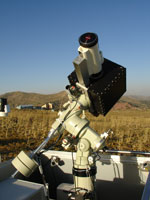
Automatic guiding system (at AZT22)
- The autoguider design and principal parameters
-
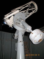
The autoguider is mounted on the fastening flange of the position ball bearing of the telescope. The construction is designed in such a way,
that the working plane of the scientific CCD camera attached to the autoguider, coincides with the calculated best-image plane of the telescope.
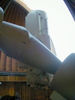
The autoguider (Fig. 5) has a two-high construction: the top and the bottom flanges are connected with the use of separate precise carriages, moving
along right ascension and declination.
(read more ...)
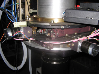
Fig.5 Autoguider at the AZT-22 telescope.
To provide smooth motion, all the carriages are manufactured with the use of ball bearing. To reduce backlashes,
the main lead screws are mounted in separate cases with the use of a binary angular ball bearing, whereas the nuts are split, with the tunable gaps.
The pitch of thread of the screws is 1 mm, and the range of motion is ±2.5 mm. The stepping motors from DELTA-KROK (Kirovograd) ДШР-56-1.8-0308, which
provide 200 steps per one revolution of the motor shaft, are used. The execution time of one step is 3 milliseconds. The drivers of these step motors
provide the microstepping regime as well.
| Table 1. Principal parameters of the autoguider |
| |
Focus 1/7.7 |
Focus 1/17 |
| guiding step, mm |
0.005 |
0.005 |
| guiding step, arcsecond |
0.09 |
0.04 |
| guiding range, mm |
±2.5 |
±2.5 |
| guiding range, arcsecond |
±45 |
±20 |
| The range for guiding right ascension star search, mm |
45 |
45 |
| The range for guiding declination star search, mm |
115 |
115 |
| The range for guiding right ascension star search, arcmin |
14 |
6 |
| The range for guiding declination star search, arcmin |
35 |
15 |
| The limiting magnitude of suitable for guiding stars, mag |
13 |
12 |
A two-coordinate carriage is mounted on the bottom autoguider flange, which carries a small CCD camera, destined for real-time measurements
of coordinates of a relatively bright star (guiding star) near the observed object. This miniature WATEC LCL 902K CCD camera (Fig. 6) has high
sensitivity and works in the TV format with the exposure time of 40 milliseconds.
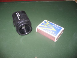
Fig.6 The miniature CCD camera of the guiding system
The light from a guiding star is directed to this camera with
the use of two small mirrors. During the search for a suitable guiding star, the carriage with the TV camera is driven by small step motors
ДШР40-1.8-1004 supplied by the same company DELTA-KROK. The range of motion of the carriage with the TV camera is 115 mm along the right ascension
axis and 45 mm along the declination axis, the range ends are controlled by limit switches (Fig.7). The analog signal passes to the controlling computer,
equipped with the analog-digital converter card.
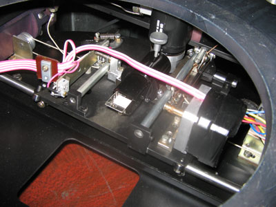
Fig.7 The carriage for moving the guiding CCD.
The autoguider is designed for the use in the short-focus mode (1/7.7, without correcting lens) or in the long-focus mode (1/17, with a correcting lens)
of the AZT-22. The main autoguider parameters are given in Table 1.
- Operational algorithm of the automatic guiding system
The operational algorithm of the automatic guiding system includes the following procedures:
- Setting of all the carriages into the initial position.
- Positioning of the telescope to a target object.
- The search for a star suitable for guiding near the target object is fulfilled by the drives of the TV camera carriage.
- Accumulation of images of a guiding star during 10 seconds for estimation of atmosphere parameters in a particular night (is used for calculation of the guiding star coordinates later );
- Beginning of the autoguider work: accumulation of a signal from the guiding star with the subsequent calculation of coordinates of a star centroid and correction of positions of autoguider carriages with the use of stepping motors; the working range is from 5 corrections per second to 1 correction during 5 seconds.
- Beginning of the exposure for the target object.
(read more ...)
The following data are displayed at the monitor of the controlling computer: the guiding TV camera field of view,
a fragment of this field under processing, mutual positions of the main CCD camera and the guiding TV camera, relative
coordinates of the guiding TV camera position, the integration time of the TV signal, the total time of integration,
and the values of corrections that have been accomplished already.
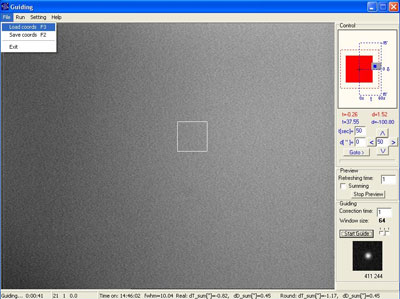
Fig.8 Interface of automatic guiding system
- The control device of the autoguider
-
The control device of the autoguider is designed for moving the autoguider carriages and guiding TV camera along the two mutually
perpendicular directions using commands from a personal computer. The structure chart of the unit is shown in Fig.9.
(read more ...)
Fig.9 The structure chart of the autoguider driving unit: БП –power supply, ШД1-ШД4 – steeping motors,
Д1 – Д4 – drivers of steeping motors, М1—М4 – electromagnets, К1-К8 – limit switches.
The unit consists of an electronic control module, power supply (PS), four stepping motors (ШД1-ШД4), four drivers of stepping motors (Д1-Д4),
eight limit switches (К1-Л8) and connecting cables. In addition, as the need arises, up to four electromagnets (М1-М4 in Fig. 9), designed for
the firm fixture of the guiding camera or any other supplementary purposes, can be connect the unit up. The moving of the carriage is performed
with the use of two steeping motors ШД-56, moving of the guiding camera - by ШД-56 and ШД-40 motors. The required stabilization of the current in
windings of the steeping motors is carried out by four drivers of steeping motors (Д1-Д4), each of them is manufactured on the base of a special А3977
chip from the ALLEGRO company. The use of this chip permits to set, in case of a need, different regimes of stepping motors: one step, a half a step,
1/4 and 1/8 of a step. The power supply of the unit is provided by a stabilized AC source with the output voltage of 30V. The control unit of the
autoguider, together with the power supply, are settled in the immediate vicinity of the autoguider at the telescope tube. The unit is controlled by
the driving routine from a PC through the PC COM-port using the RS232 protocol. The permissible length of a connecting cable is up to 15 m.
In August 2006, the new system for automatic guiding was installed at the AZT-22 telescope. The testing of the system had shown it to highly efficient,
reliable and user-friendly. The system for automatic guiding was installed in the 1/7.7 focus in November 2006, and since that time, all the observation at
the telescope are carried out with the use of the autoguider.
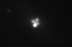
Fig.10 The image of gravitational lens Q2237+0305 (Einstein Cross), obtained at the AZT-22 telescope
with the use of the new system of automatic guiding. The size of a star image (FWHM) is 0.65" in the 20-minutes exposure.
Images of the gravitational lens Q2237+0305 and the galaxy IC342 obtained with the autoguider in operation,
are given in Fig. 10 and Fig. 11. Analysis of these images had shown, that not only the main problem was eliminated,
related to imperfection of the clock driving system of the telescope, which did not permit to use the exposures longer
than 5 minutes because of an unacceptable large value of image blurring. The new system turned out to be also effective
in eliminating the low-frequency (up to 1Гц) shifts of image, caused by influence of the Earth atmosphere. This resulted in
an increase of the limiting magnitude of the telescope and in achieving high quality of observing data: the size of a star
image became as small as 0.7″ during the exposure time up to 30 minutes.
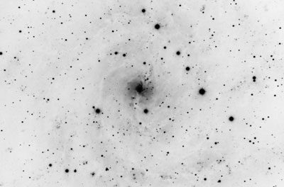
Fig.11 An image fragment of the galaxy IC 342 obtained at the AZT-22 telescope with the use
of the new system of automatic guiding. The exposure time is 30 minutes. The size of a star image (FWHM) is 0.8".
It should be noted, that the images given in Fig.10 and Fig.11 have not been obtained during the nights with the
superb seeing conditions the Maidanak observatory is famous for. In general, the weather during the summer-autumn seasons
in 2006 was not typical for this site. Relatively small number of clear nights and high instability of the atmosphere in few
clear nights prevented from demonstrating the capability of the AZT-22 telescope with the new guiding system in full measure.
- ZEISS-1000
 |
 |
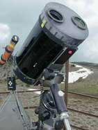
Zeiss-1000 1m telescope
Optical configuration:
Cassegrain f/13, D=1.0m
Equipment:
BroCam SITe005 2000х800 CCD
|
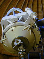
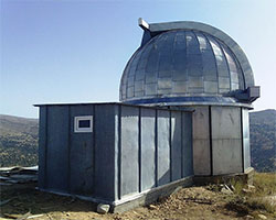
ZEISS-1000 (Carl Zeiss, Jena) telescope of the Maidanak Astronomical Observatory was installed in 1978 and has been operational since it first light gained in 1981.
Cassegrain–Ritchey–Chretien–Coude optical layout of the telescope was built with minimum effort to reach greatest possible universality and efficacy for such research projects as:
a) photographic wide field survey and detailed analysis of individual objects by a photometer or spectrometer, b) usage of stationary auxiliary devices.
English mount of a telescope is suitable for all astronomical sites with geographical latitudes within -55° and +55°.
(read more ...)
Discrete control system initially was used to control the telescope. The idea to modernize and automate the telescope was first promulgated in 2003.
Then in 2005 the new computerized control system was installed which greatly simplified and automated the observation process. The new control system included pointing,
target selection using graphical interface based on all-sky GSC, DSS and USNO A or B catalogs, tracking and focusing, visual control of telescope and its systems as well
as monitoring various site parameters. Currently this control system is out of service.
ZEISS-1000 is equipped with an LN cooled back-illuminated “BroCam SITe005” CCD camera with 2000x800 pixels which has been used for various scientific photometric and spectroscopic programs.
| Basic specifications of a telescope |
| Diameter of the main mirror, mm |
1016 |
| Spectral range, mkm |
0.3 - 10 |
| Angular resolution, arcsec |
0.8 |
| Weight of tube, kg |
4800 |
| Weight of mount, kg |
12000 |
| The maximal weight of the equipment in Cassegrain focus, kg |
96 |
| Ritchey–Chretien system: |
| Focal length, m |
13.3 |
| Diameter of the unvignette field |
170 mm (45 arcmin) |
| Coude system: |
| Focal length, m |
36.5 |
| Diameter of the unvignette field |
76 mm (8 arcmin) |
- ZEISS-600 Northern
 |
 |
Zeiss-600 0.6m telescope
Optical configuration:
Cassegrain f/12.5, D=0.60m
Equipment:
FLI ML0580911 1024×1024
|
- ZEISS-600 Southern
 |
 |
Zeiss-600 0.6m telescope
Optical configuration:
Cassegrain f/12.5, D=0.60m
Equipment:
FLI IMG ProLine 1024x1024 CCD
|
- ZEISS-600 Eastern
 |
 |
Zeiss-600 0.6m telescope
Optical configuration:
Cassegrain f/12.5, D=0.60m
Equipment:
FLI IMG ProLine 1024x1024 CCD
|
- TAT
 |
 |
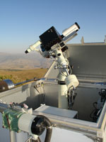
Taiwan Automated Telescope (TAT)
Optical configuration:
9-cm Maksutov-type telescope manufactured by Questar. Effective focus length is 225 sm, f=1/25 with
view angle equal to 0.62 degrees
Equipment:
Apogee Alta-U6 16-bit 1024×1024 CCD camera
The instrument is robotized up to maximum
|
The TAT Network is a global ground based network of small, identical and fully automated telescopes. The headquarters of the network is located at the
Physics Building of the National Tsing Hua University, Taiwan. Besides the prototype telescope located at the headquarters, three TATs have been deployed
at Teide Observatory (Spain), Maidanak Observatory (Uzbekistan) and Lijiang Observatory (China). The TAT network is dedicated to stellar multi-color
photometric measurements.
(read more ...)
The TAT uses a 9-cm Maksutov-type telescope manufactured by Questar. The effective
focal length is 225 cm, corresponding to an f-ratio of 25. Its field of view is 0.62. The detector is a 16-bit 1024×1024 CCD (Apogee Alta U6) and the CCD chip
is a Kodak KAF-1101E. The spatial sampling window is 2.18 arcsec per pixel.
Project manager is Prof. Dean-Yi Chou from National Tsing Hua University, Hsinchu, Taiwan. A more detailed description of the TAT can be found in
Chou et al.
(Chou, D.-Y., Sun, M.-T., Fernandez Fernandez, J., Wang, L.-H., Jimenez, A., Serebryanskiy, A., & Ehgamberdiev, S.2010, Advances in Astronomy, 2010, 4.).
The instrument is fully automated. Since it has built-in telescope and peripherals control system the telescope management and monitoring can
either be in fully automated and/or interactive regimes. The telescope is equipped with comprehensive whether monitoring station and telescope
visual control system which consists of eight (8) outside and inside video surveillance cameras. Video feed is momentarily transmitted through
Internet to ensure intermittent surveillance over equipment conditions, weather and observation process itself.
====== reference =========
Chou, D.-Y., Sun, M.-T., Fernandez Fernandez, J., Wang, L.-H., Jimenez, A., Serebryanskiy, A., & Ehgamberdiev, S. 2010, Advances in Astronomy, 2010, 4.
- DIMM
 |
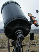 |
Differential Image Motion Monitor (DIMM)
Optical configuration:
Based on a standard Celestron-11 telescope with a 279 mm primary mirror and a focal length of 2800 mm
Equipment:
ST5 CCD (SBIG, Santa Barbara Instrument Group)
|
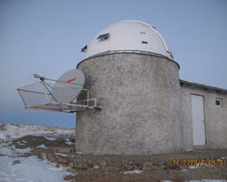
DIMM stands for Differential Image Motion Monitor, originally designed at ESO (Sarazin & Roddier 1990).
It was used at Maidanak during the period 1996-2006. It is based on a standard Celestron-11 telescope with a 279 mm primary
mirror and a focal length of 2800 mm. The pupil is covered by a mask with two circular 80 mm diameter apertures 200 mm apart.
The mask is fixed above the Schmidt corrector plate. A prism with a wedge angle of 195” (arcseconds) is added to one of the holes.
The light detector is an ST5 CCD array with 10 x 10 µm square pixels. The instrument produces two stellar images on the detector, 121 pixels
apart at the nominal focus (the plate scale is 0.73 arcseconds per pixel) and rms of differential movement is used to estimate zenith seeing
every few minutes for the wavelength of 0.5 µm.
The DIMM instrument has been modified in 2007 using another CCD array and new controlling and acquisition software.
Since that time it is used for site-testing of several Uzbekistan observatories, including Maidanak. At the moment, it is in Tashkent.
- AMT-1
 |
 |
AMT-1 0.5m telescope
(AstroTel-Maidanak Telescope, amateur)
Optical configuration:
Corrected Ritchey–Chretien f/8, D=0.51m
Equipment:
Apogee Alta-U16M CCD
|
|
|
| CCD Detectors |
|
|
|
- SI 600 Series
- (provided by Seoul National University, Korea)
SI 600 Series 4096x4096 CCD (SNUCAM) at AZT22 scope
Type: Spectral Instruments 600 Series (600-627)
CCD size: 4096x4096
Readout noise: ~4.7 e- (200 KHz)
Gain: 1.45 (200 kHz)
Cooling: -108 ºC
Documentation: ...
Filters: Bessell UBVRI or BVRI
- FLI MicroLine
- (provided by ISON project)
FLI MicroLine 09000-65 3056x3056 CCD at AZT22 scope
Type: ML09000
CCD size: 3056x3056
Readout noise: ~10 e- (1 MHz)
Gain:
Cooling: -60 ºC
Documentation: ...
Filters: Bessell UBVRI or BVRI
- BroCam SITe005
- (provided by )
BroCam SITe005 2000х800 CCD at Zeiss-1000 scope
CCD size: 2000х800
Read Noise (eˉ/pix): 5.5
Gain (eˉ/ADU): 1.16
Cooling: -100 ºC
Documentation: ...
Filters: Bessell UBVRI or BVRI
- FLI ML0580911
- (provided by Keldysh Institute of Applied Mathematics)
FLI ML0580911 1024x1024 CCD at Zeiss-600 (Northern) scope
Documentation: ...
Filters: Bessell UBVRI or BVRI
- FLI IMG ProLine PL4710-1-BB
- (provided by UBAI)
FLI IMG ProLine PL4710-1-BB 1024x1024 CCD at Zeiss-600 (Southern) scope
Imaging system with E2V CCD41-10-1-371
Grade 1 back-illuminated sensor
Triple TEC cooling, air cooled base
AR coated quartz window
FLI Research Grade UBVRI filters, 50mm diameter
Precision Digital Focuser (PDF)
- Apogee Alta-U16M
- Apogee Alta-U16M 4096x4096 CCD at AMT-1 scope
Filters: Bessell UBVRI or BVRI
- Apogee Alta-U6
- Apogee Alta-U6 at TAT scope
16-bit 1024x1024 CCD (Apogee Alta-U6) and the CCD chip is a Kodak KAF-1101E.
Filters: without Filters
- SBIG ST-5
- SBIG (Santa Barbara Instrument Group) ST-5 (TC-255) at DIMM scope
Filters: without Filters
FILTERS: Bessell UBVRI or BVRI
|
|
|